

Actuator for Screwed Globe Valve ILJA-06
The actuator series ILJA-06 has been designed to control the screwed globe valves series ILJV up to DN40. The actuator is equipped by a bidirectional synchronous motor at 600 N and available in ON-OFF, floating and proportional version. Fast and easy assembly. The actuator is equipped, for the proportional version, with a button for self-adjustment. The on-off switch is fitted with magnetic clutch.
Retail Price:
$ 0
Remaining Stock
Category:
Globe Valve Actuator Series
Keyword:
Actuator for Screwed Globe Valve
Service Hotline:+86-10-8775-5626
Inquiry Email:jocko@ilamps-trade.com
- Product description
- Technical data
- Measurement
-
- Commodity name: Actuator for Screwed Globe Valve ILJA-06
The actuator series ILJA-06 has been designed to control the screwed globe valves series ILJV up to DN40. The actuator is equipped by a bidirectional synchronous motor at 600 N and available in ON-OFF, floating and proportional version. Fast and easy assembly. The actuator is equipped, for the proportional version, with a button for self-adjustment. The on-off switch is fitted with magnetic clutch.
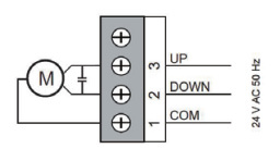
Electrical Wiring
ILJA-06 (on-off, floating)
1: 24 V AC (common)
2: 24 V AC Stem down (direct way open)
3: 24 V AC Stem up (direct way close)
ILJA-06M (proportional)
Terminal J1:
1: 24 V AC
2: Common
3: Input signal. 4...20 mA (2...10 V DC) / 0...20 mA (0...10 V DC).
W1 e W2 must be set according to the input signal.
4: Feedback signal. There is a signal 0...10 V DC or 2...10 V DC depending on the setting of W2.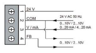
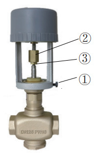
Installation
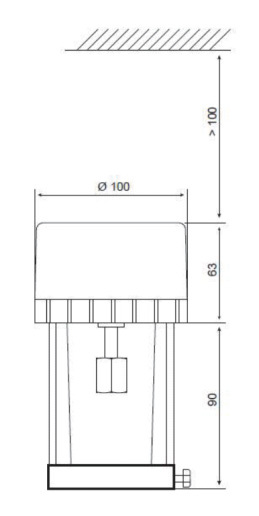
• Place motor on the valve and, having placed in seat, tighten the locking screw (1).
• Screw the brass nut of the motor shaft on the valve stem (2) and tighten the counter nut (3).
• Make the electrical connections as shown in the previous diagrams and (only for AVG6M) provide for the jumper settings.
Setting ILJA-06M
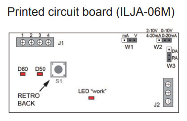
W1: mA / V DC. Allows to choose whether the input signal is in voltage or in current. This jumper must be set along with W2 to select the input signal to J1.
W2: 4...20 mA (2...10 V DC) / 0...20 mA (0...10 V DC). This jumper must be set with W1 to select the input signal to J1.
W3: Reverse operation. Moving the jumper inverts the logic of operation compared to the input signal.
LED Status indicator (work):Normal operating status: flashes slowly (1 sec on, one sec off). During the self-adjustment of the actuator on the valve (after pressing S1 for at least 3 sec): flashing quickly (for 0.25 sec on , off 0.25 sec)
Self-adjustment in an error state: blinks twice quickly and off for a long time (on 0.25 sec, off for 0.25 sec,twice, then off by 1.25 sec)
LED indication of the rotation direction of the motor:
When the LED D60 lights up, the valve shaft moves downward. When the valve shaft reaches the bottom and hold the position for 25 sec, the LED turns off.
When the LED D50 lights up, the valve shaft moves upward. When the valve shaft reaches the top and hold the position for 25 sec, the LED turns off.Self-adjustment of the actuator to the valve. Each actuator must be adapted to the valve to which it is coupled.
Press and hold the “S1” key for 3 sec, the actuator automatically will enter the self-adjustment. The LED “work” is flashing rapidly (on 0.25 sec., off 0.25 sec.). The valve shaft moves down to the bottom, and then maintains the position for 25 sec and then move upward until the upper point. The self-adjustment does not end until the valve shaft does not hold the final position for 25 sec.
To self-adaptation occurred (the previous data is overwritten), the actuator returns to normal operation. Otherwise (the previous data is not overwritten),will be reported the failure of the state of self-adjustment (on 0.25 sec., off 0.25 sec., twice, then off by 1.25 sec.). You can hold down the “S1” key for 3 sec to retry the process of self-adjustment, or reboot (power cycle) of the actuator to return to normal working state.Possible errors of self-adjustment:
1: It occurs in the case where the stroke is reached less than half the nominal stroke.
2: The connection of the potentiometer is wrong (terminal J2). Correct way: when the valve shaft is downward the potentiometer has the maximum value, when the valve shaft is upward the potentiometer has the minimum value. -
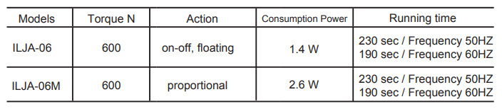
Technical Specifications
Power supply: 24 V AC 50/60 Hz
Electrical connection: Screw terminal
Torque: 600 N
Max. stroke: 20 mm
Running time: See schedule
Materials: ABS cover, self-extinguishing
Protection degree: IP54
Protection class: II
Working range °C: -10...+50°C
Storage temperature and humidity: -40...+50°C, 1...95% RH, non-condensing
Fluid temperature: ≤ 150°C
Maintenance: Free
-
Dimensions
Related Documents
-
File size: 1.8MB


