

Flow Switch ILH333
The ILH333 Flow Switc has Are Single-Pole, Double-Throw (SPDT) flow switches that are used in liquid lines carrying water ,ethylene glycol, or other liquids not classlfied as hazardous. They can be wired to energize one device and de-energize an-other device powered from the same source when liquid flow either exceeds or drops below the set flow rate. Note: The ILH333 Flow Switch can not be used where the liquid in the pipes will drop below the liquid’s freezing point , causing an internal freeze-up.
Retail Price:
$ 16
Remaining Stock
10000
Category:
Automatic Control Terminal Product Series
Keyword:
Flow Switch
Service Hotline:+86-10-8775-5626
Inquiry Email:jocko@ilamps-trade.com
- Product description
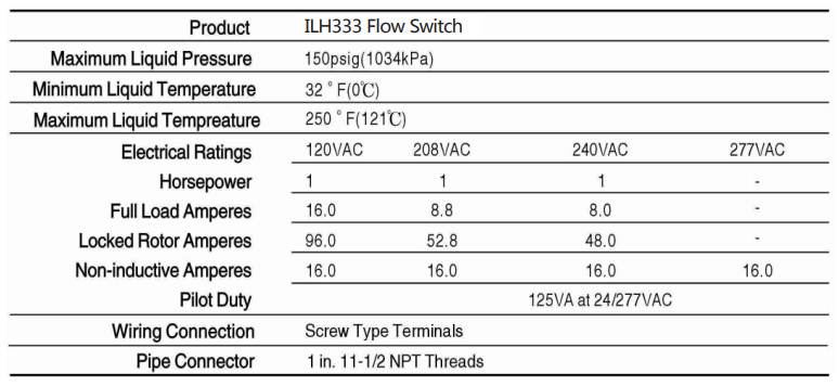
- Technical data
- Measurement
-
- Commodity name: Flow Switch ILH333
The ILH333 Flow Switc has Are Single-Pole, Double-Throw (SPDT) flow switches that are used in liquid lines carrying water ,ethylene glycol, or other liquids not classlfied as hazardous. They can be wired to energize one device and de-energize an-other device powered from the same source when liquid flow either exceeds or drops below the set flow rate. Note: The ILH333 Flow Switch can not be used where the liquid in the pipes will drop below the liquid’s freezing point , causing an internal freeze-up.
Installation
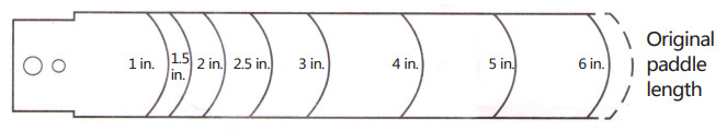
Flgure 1: Trimming Template for the EXtra Paddle
IMPORTANT: To allow the switch to detect changes in the flow condition, the paddle must not touch the pipe or any restrictions in the pipe.
CAUTION: Equipment damage hazard.
To avoid damaging the switch, do not tighten the switch to the tee by grasping the switch enclosure. Use only the wrench flats provided.• Screw the flow switch in position so the flat of the paddle is at a right angle to the flow. The arrow on the side of the case must point in direction of the flow.
• The switch should be mounted so the terminals or wire leads are easily accessible for winng.
Note: These flow switches must not be subjected to water hammer. If a fast-closing valve is located downstream of the flow switch, a suitable water hammer arrester must be used.
Adjustment
CAUTION: Improper operation hazard.
The switch is factory set at approxi-mately the minimum flow rate Do not set lower than the factory setting as this may result in the switch failing to return to a’no flow’position.CAUTION: Equipment damage hazard.
Sealed settings (screws marked with black paint) are notintended to bechanged. Adjustment attempts may damage thecontrol or cause loss of calibration, voiding thewarranty.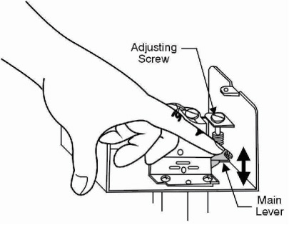
Flgure 2: Minimum Adjustment
To adjust the setting of the flow switch:
1.Remove the ILH333 cover.
2.For higher flow rates, turn the adjusting screw clock-wise. To lower the flow rate after after it has been raised from the factory setting, turn the adjusting screw coun-terclockwise.
3.Check to see that the flow switch is not set lower than the factory setting by depressing the main lever nu-merous times. If the lever fails to “click” upon return at any time, turn the adjusting screw clockwis until the lever clicks upon return every time.Checkout Procedure
The circuit betweenthe red and the yellow leads (termi-nals) will close when sufficient liquid flows through the pipe to trip the ILH333. A low flow indicator light or signal, when used, will activate when the liquid flow decreases or ceases.
Before leaving the installation, observe at least three complete oper ating cycles to be sure that the ILH333 and the system to which it is connected are functioning correctly.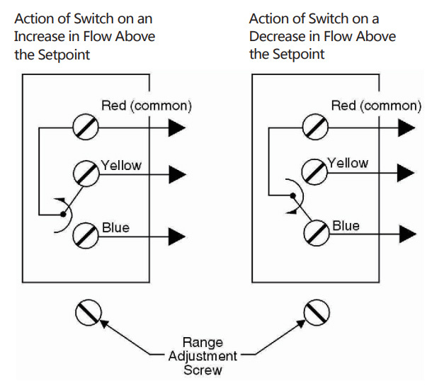
Flgure 3: Switch Action
Wiring
WARNING: Shock hazard.
To avoid possible electric shock or dam-age to the equipment, disconnect the power supply before the wiring connec-tions or adjustments are made. -
Specifications
Condit Connection One 7/8 in.(22mm)Hole for 1/2 in.Conduit with 1-3/32in.(28mm) knockout Ring for3/4 inConduit.
Typical Flow Rates
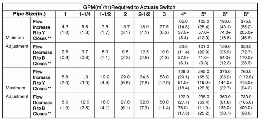
* Flow rates for these sizes are calculated.
* GPMfigures are for a switch with a 6 in.paddle.For4in.And 5in.Line pipe,the6in.Paddle is trimmed to a 4 in .length,respectively.
** For switching action,refer to Figure 3. -
Model
Previous:
Next:
Related Documents
-
File size: 5.5MB


